File system design case studies
last update: March 23, 2012
You can tune a file system, but you can't tune a fish.
— tunefs(8) man page
Introduction
We've studied various approaches to file system design. Now we'll look at some real file systems to explore the approaches that were taken in designing them. The goal here is not to look at the details of each file system but rather to get an understanding of how each design tried to introduce specific improvements.
Unix File System (UFS)
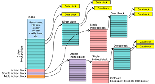
Figure 1. UFS inode block pointers
We examined the Unix File System's approach to managing inode and file blocks in the previous section as an example of indexed allocation. UFS introduced the inode-based file system. Each inode is a fixed size and the entire set of inodes is preallocated when the file system is first initialized. This makes it easy to locate any specific inode. An inode contains the file's metadata as well as 10 block pointers and one each of an indirect, double indirect, and triple indirect block. The fields within a UFS inode include:
- file owner, group owner
- file type (regular file, directory, character device, block device, FIFO)
- access permissions
- times: create, last access, and last modification
- number of links to the file, which is the number of file names in the directory that refer to this inode
- file size or major/minor numbers if the file is a device
- file data location: ten direct blocks, one indirect block, one double indirect block, and one trible indirect block
Figure 2. UFS Disk Layout
Like most file systems, UFS starts off with a superblock. The superblock contains:
- Size of file system
- Number of free blocks
- list of free blocks (including a pointer to free block lists)
- index of the next free block in the free block list
- Size of the inode list
- Number of free inodes in the file system
- Index of the next free inode in the free inode list
- Modified flag (clean/dirty)
Directories are files that contain a simple linear array of 16-byte structures. Each structure contains 12 bytes for a file name and four bytes for an inode number.
Free space is managed as a linked list of blocks. The superblock contains an array of a few free disk blocks as well as a pointer to a block that that contains a sequence of block numbers representing free blocks in the file system. The start of this block has a block pointer to the next block of free block numbers (which, in turn, has a link to the following block of free block numbers). This the linked allocation structure that we saw earlier. While it didn't make sense for managing file blocks because seeks become prohibitively costly, the free block list does not require seeks. The superblock contains an index to the first unused element in the first free block. When a block is allocated, the block number is read and the index is advanced.
The problem with this approach is that, as files come and go (and their blocks are allocated and released), eventually the list becomes a mostly random collection of blocks. When a new file is allocated with a random set of blocks, reading each successive block of a file will most likely require a seek on the disk. This is known as file fragmentation. Instead of having a file's blocks allocated contiguously (or generally close to each other), they are scattered throughout the file system. Since most files are read sequentially (from the beginning of a file to the end), fragmentation has a huge impact on performance in disk-based file systems. Disk seeks, which require the head to move from one track to another, take considerable time. Reading adjacent blocks is much, much faster than seeking to another part of the disk to read a block. Typical performance of UFS was often only 2–4% of the raw disk bandwidth!
UFS was not, by any measure, a high-performance file system. Its main virtue is its simplicity. It introduced the ability to store devices within the file system. A device is an inode that contains no data blocks and no file size. A mode bit in the inode identifies the file as a device special file and the inode stores the major and minor numbers that identify the device to the kernel.
The lasting legacy of UFS is the inode and the structure of direct and varying levels of indirect blocks.
Incidentally, fragmentation was a significant problem with FAT-based file systems as well. Microsoft includes a disk defragmentation utility that shuffles file data among disk blocks to try to get as much contiguous allocation as possible.
BSD Fast File System (FFS)
BSD (Berkeley Standard Distribution) is the derivative of Unix from the University of California at Berkeley. They looked at the shortcomings of UFS and created a new file system, called the Fast File System (FFS), to address what they saw were the biggest faults of the file system.
Larger blocks
The first are they addressed was the block size. Instead of using UFS's 512-byte blocks (or, later, 1024-byte clusters), they clustered blocks and picked a logical block size of 4096 bytes or larger. The cluster size is recorded in the file system's superblock. Just doubling the block size resulted in over a twofold performance gain! The benefit is that direct blocks in an inode now address twice the storage before you need to read an indirect block (which also addresses twice the storage). A 4 KB block allows one to have 4 GB files with only two levels of indirection. Because contiguous allocation within the cluster is guaranteed, even if the poor block allocation strategy of UFS is employed, the amount of fragmentation in a file is now reduced by a factor of two.
The problem with bigger blocks was that internal fragmentation increased. A lot of files were extremely small and many blocks were allocated because they were part of the cluster but remained unused. When this file system was designed, this was a significant side effect that contributed to a lot of wasted disk space.
BSD's solution to this was to manage fragments within a block down to the native block size of 512 bytes. Free space on the disk is kept track of via a bitmap, which tracks individual blocks rather than clusters. A small file may have just one fragment, a partial cluster, allocated to it. As the file grows and exceeds its fragment size, a larger fragment is allocated and the file's data is copied over to that larger fragment. Eventually the fragment is copied over to a full block. Hence, a file contains zero or more full blocks and possibly one fragmented block. Of course one wants to avoid having copying fragments into larger fragments as a file grows. BSD allowed user programs to find the optimal block size (cluster size) so they can use it to optimize their I/O. The standard I/O library (libc, which contains functions such as fopen, fread, fwrite, fgets, etc.) takes advantage of this. Also, extra writes are avoided by caching data in the buffer cache. Even if a process does single-byte writes, their result will usually be cached until entire clusters are ready to be written to the disk.
Cylinder groups: minimize head movement
The second effort to improve performance was to minimize disk head movement. Since disk seek time is high compared to reading blocks that do not require a seek, the goal is to keep files close to their inodes. With UFS, all inodes were lumped at the very beginning of the file system. Blocks for data files and directories were allocated essentially randomly from the pool of free blocks (from the free block list, but the list eventually got randomly scrambled). With the FFS, the goal is to keep related files, directories, and their inodes close together.
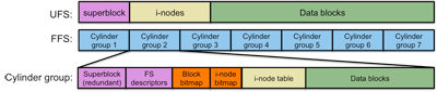
Figure 3. FFS Disk Layout
As we saw earlier, a cylinder is a collection of all the blocks that share the same track number on all the heads of a disk. These are all the blocks that could be read with no disk seeking (hence, quickly). The FFS defined a cylinder group as a collection of nearby cylinders. A cylinder group is the group of all blocks where successive blocks in the same cylinder group can be accessed very efficiently.
Instead of lumping all the inodes together at the start of the file system, the BSD FFS replicates the file system structure for each cylinder group (figure 3). Unless it's absolutely not possible, the file system allocates data blocks to inodes within the same cylinder group. A bitmap within each cylinder group keeps track of free disk blocks within the cylinder group. Another bitmap keeps track of free inodes within the group.
Splitting the file system into multiple chunks makes locating inodes a little bit more difficult. We can no longer compute the block containing the inode directly from the inode number. Instead, we need to know how many inodes each cylinder group has. To handle this efficiently, the file system module needs to keep a table of cylinder groups.
Optimized sequential access
Bringing all the related blocks of a file into close proximity with each other as well as well as the file's inode improves both sequential as well as random access. Since the bulk of file accesses are sequential, FFS adds extra optimizations for sequential access.
The FFS block allocator tries to allocate adjacent blocks where possible [1]. When the file system needs to allocate a block for a file, it will try to pre-allocate eight adjacent blocks. This achieves good performance under heavy loads since it makes the allocator run faster and improves sequential read/write performance on files.
Finally, the file system tries to deduce whether a file is being accessed sequentially and do either a large read or a prefetch. If two or more logically sequential blocks are read from a file, the FFS module assumes that a sequential read is taking place and will request one large I/O on the entire range of sequentially-allocated blocks in the file. Otherwise, if there are no more sequential blocks then the module will schedule a read-ahead, a request for the next disk block in the file. A read-ahead is an anticipatory request for a disk block. We don't know whether we'll need it but believe there's a good chance that it will be needed. By the time we do need it, the hope is that the data has already arrived or is being read into memory.
Improved fault tolerance
Notice in firgure 2 that the superblock is present in each cylinder group. The is done for redundancy. Since the superblock is so crucial to defining the core operational parameters of the file system, it is replicated in each cylinder group.
Because each cylinder group is essentially self-sufficient, containing free block maps, inodes, and blocks, even if a large section of the disk loses data, all data in the file system is not lost. Undamaged cylinder groups should still have their full structure.
FFS tries to further improve fault tolerance by imposing strict, synchronous (immediate) writes of file system metadata. Because a file's metadata (inode) is so crucial to the integrity of a file, changes to metadata are not buffered but immediately written to the disk. This limits I/O throughput somewhat but was deemed desirable to help preserve file system integrity.
FFS, however, is by no means a fault-tolerant file system. It still requires up to five complete passes over file system structures to verify the integrity of the file system and attempt to repair any inconsistencies.
Directories and inodes
Directory files still contained a linear list of filenames. Unlike UFS, each entry is no longer a fixed length. Instead each entry contains a length field and file names can be up to 255 bytes long.
The inode structure is largely the same as with UFS, except that the number of direct blocks has been increased from 10 entries to 12.
Symbolic links
FFS introduced the concept of symbolic links. Symbolic links are allocated and structured just like regular files but have a flag set in the inode that identifies them as symbolic links (much like directories are just regular files but have a flag that identifies the inode as being a directory). The motivation behind symbolic links was that hard links could not be used for directories (for fear of loops developing in the file system hierarchy) and they could not be created for files that reside on another file system (a hard link is just another name that points to an inode; there's no way for a directory entry to identify that the inode is on a different file system).
Performance
Overall, the Fast File System's uses about 14-47% of the raw disk bandwidth. While this may not seem like much, it is a huge improvement over the 2-5% disk bandwidth utilization of UFS.
Linux ext2
Linux's ext2 file system is an adaptation of the BSD Fast File System but with three basic changes.
- No support for fragments
- Fragments made a lot of sense in the 1980s when both average file sizes and disk space were smaller. The percentage of files that that occupy less space than a cluster is much smaller. Moreover, wasted space is not as precious a commodity. Writing to files is faster if one does not have to worry about allocating fragments and then copying the data to bigger fragments and then to blocks. The ext2 file system uses a single cluster size for all allocations.
- Block groups instead of cylinder groups
-
Instead of dividing the partition (or disk) into cylinder groups, ext2 divides the partition into fixed-size block groups. This is essentially the same as cylinder groups except that cylinders no longer have a useful meaning in modern disks (figure 4).
- Aggressive caching
- FFS tried to make the file system more resilient to failure by writing out any metadata immediately instead of caching it in the buffer cache and doing a delayed write. The approach of ext2 is to cache aggressively, perform all operations in memory, and leave them in memory until the buffer cache gets flushed. This increases the chances of file system inconsistencies arising if the file system is not cleanly unmounted but the rationale was that this hardly ever happens and the file system should be performance-optimized for the more common case of no spontaneous shut-downs.
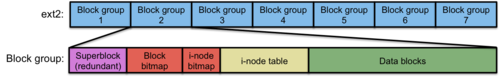
Figure 4. ext2 Disk Layout
The inode and directory structure is essentially unchanged from FFS.
In summary, ext2 is a minor change over FFS. However, because of aggressive caching and the lack of fragment managing, ext2 is usually considerably faster than FFS, even if it's largely the same.
Linux ext3: journaling
The ext3 file system is essentially the same as the ext2 file system but with support for journaling The goal of journaling is to improve the reliability of and the time spent in verifying and repairing the consistency of a file system. With large file systems, such as multi-terabyte ones, it can take hours to validate the integrity of a file system after an abnormal unmount (such as after a system crash or a spontaneous loss of power).
To understand the goal of journaling, let's consider the operations that take place when, for example, we write to a file and add a new data block. The bitmap of free data blocks gets updated (the block is no longer free); The data block contents are written; and the inode gets updated with a new block pointer and file size. For larger files, both an inode and indirect block will get updated.
Before we start these operations, our file system is in a consistent state. After these operations are performed, the file system is also in a consistent state. This means that bitmaps truly represent unused blocks, files point to valid inodes, each inode has at least one reference to it, disk block pointers are valid, etc. If every single one of these operations does not complete, however, the file system will be left in an inconsistent state:
- If the inode is not updated with the new data block then the new data does not become part of the file.
- If the inode is not updated with the new file length then the new data will be ignored.
- If the free data block bitmap does not get updated then the block can be re-allocated to another file.
- If the data is not written to the data block then the file will contain garbage.
The consistent update problem is the challenge of performing all these related operations atomically. For the file system to be consistent, either all of the operations have to take place or none of them should take place.
Journaling
Journaling is also known as write-ahead logging and originates with databases. With journaling, we keep a transaction-oriented journal of changes. We record the start of a transaction, the actions involved in that transaction (along with the data that goes along with the actions), the end of a transaction, and commit all that to disk. For example:
- Transaction-begin
- New inode 779 [inode contents]
- New block bitmap, group 4 [bitmap block contents ]
- New data block 24120 [data block contents ]
- Transaction-end
Once this journal is written to the disk, we send the same operations again onto the actual file system. If all goes well and the system is not shut down abnormally, then we don't need this transaction entry any more. However, if a crash (or spontaneous removal of the file system) happens at any time after the log was committed to the journal, the crash recovery process will replay the log prior to mounting the file system. This is called redo logging. The log contains all the data that we need so we have no information loss and can reconstruct the data. Moreover, the log tells us which disk blocks may have been affected (modified or not) so we don't have to search the whole file system looking for inconsistencies. If the system died before the journal transaction was written, the recovery process will see that there is no "transaction end" marker written to the log and will ignore the partial transaction. Since the transaction was not fully logged, we know that no modifications took place to the file system yet, so the file system is still in a consistent state.
We have to be careful with how we write the journal. It's tempting to schedule a number of disk writes but we don't know what order the disk controller will schedule the actual block writes. We have to ensure that we account for the fact that the system can be shut down at any point in time. If a "transaction-end" marker is written prior to the logs of the data that's related to that transaction, the recovery process may think a transaction is fully logged, not realizing that the data is garbage.
A safer approach is to write all the journal blocks except the "transaction-end" marker. When the disk has acknowledged those writes, then we write the "transaction-end" marker. After that, we start writing the file data.
Cost of journaling
It's pretty obvious that there's a significant cost to journaling. Every disk block gets written twice: once as a journal log and again to the actual disk block. Moreover, since the journal will be a circular buffer of blocks in one area of the disk, we also incur a disk seek to do the write.
One optimization is to avoid not write the file data to the journal but still log metadata and bitmap data. Our log may now look like this:
- Transaction-begin
- New inode 779 [inode contents]
- New block bitmap, group 4 [bitmap block contents ]
- Transaction-end
What happens to the data? To preserve data integrity, we sequence our operations and write the data block(s) first. Then we write the transaction record as before, waiting for all outstanding data and journal operations to commit before writing the "transaction-end" marker. Then we modify the metadata. If the data was just a modification of a block already in the file, then the change will be in the file system whether or not the log is complete. If the data was an additional block to the file (as in our example), and the transaction is fully recorded, the file's data has already been written and the log replay will set the metadata to their proper values. If the transaction was not fully recorded than the data block with updated contents is still marked as free and the file system remains consistent. The only snag with this approach is if we're modifying existing data rather than adding new data to the end of a file. If the system dies before the transaction log is written, you will not know whether the data modifications are in place in the file or not. The file system will remain consistent but the file contents may be unexpected in this case. This type of optimized journaling is called ordered journaling and is considerably faster than the full data journaling that we described earlier.
ext3 journaling options
The ext3 file system offers one of three types of journaling if journaling is enabled:
- journal: This is full data journaling. It's the most reliable but slowest since we are writing out over twice the data to the disk.
- ordered: This writes data blocks first, then journals the metadata, terminates the transaction, and then writes the metadata. It will keep the file system in a consistent state but in some cases may lead to partially modified files.
- writeback: This journaling does metadata journaling but with no strict sequencing of writing the data blocks first. Recently modified files can be corrupted after a crash. It's the fastest of the options and a weak form of journaling since it can lead to data corruption. However, it leads to no more corruption than with non-journaled file systems and saves on recovery time.
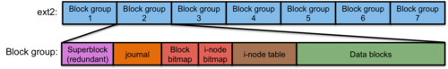
Figure 5. ext3 Disk Layout
Figure 5 shows the layout of the ext3 file system. You'll notice that it looks just like the ext2 file system except that every block group gets a journal file (circular buffer).
The only other significant change in ext3 over ext2 was better support for huge directories. Instead of an FFS-style linear list, ext3 offers the option of using a data structure called an HTree, which is a wide, balanced tree structure similar to a B-tree. The system supports 32,000 entries per directory and it's far more efficient to create, delete, and search directories.
Linux ext4
The ext4 file system is a successor to ext3. The basic structure is the same in many ways: inodes, journaling area, block groups, etc. The key differences are:
- Large file system support.
- The file system can now support disks up to 1 exabyte (1018 bytes), with file sizes up to 16 TB. In contrast, ext3 supported file systems up to 32 TB and files up to 2 TB.
- Extents
- Extents are used instead of block maps. This is significant. Instead of block numbers in the inode, ext4 uses extents. An extent is a starting block number along with a count of contiguous blocks. A big advantage of extents is that a lot of blocks will be allocated contiguously (especially on new or not-very-full disks) and they can be represented with a smaller amount of extents than than block numbers. Block numbers will, of course, require a block number entry per allocated block. One extent can map up to 12 MB of space, using a 4 KB block size. An inode contains 4 extents per inode. Instead of indirect and double indirect blocks, additional extents ones are stored in an Htree (a constant-depth tree similar to a B-tree). The reason for using an Htree instead of a linear list as block (cluster) numbers in inodes is to make the search for block numbers quick for random seeks into a file. Block numbers refer to a fixed amount of file space, so finding the byte offset for byte n means finding the [n/(cluster_size)]th block number. Each extent, on the other hand, refers to a varying number of blocks.
- Preallocation of empty space in a file
- If an application allocates unused disk space (e.g., seeking to some position in a file and then writing), ext4 can handle the preallocation of disk space without actually writing 0's into the file.
- Delayed allocation of disk space
- The ext4 file system can also delay allocating disk space until the last moment, which can improve performance. The allocation takes place when the buffers for the file are flushed to the disk. Delayed allocation increases the chance that more contiguous blocks will be allocated.
- Even larger directories
- Ext4 supports over 64,000 entries per directory versus 32,000 in ext3.
- Journal checksums
- In addition to ext3-style journaling, ext4 adds journal checksums, which allows the operating system to ensure that journal data is not corrupt.
- Faster checking
- Ext4 provides Faster file system checking by skipping unallocated block groups.
- Nanosecond timestamps
- Timestamps in an inode (last modified time, last accessed time, created time) were stored to a one-second granularity in ext3 and previous file systems. In ext4, they are stored to within one nanosecond.
NTFS
N.B.: This coverage of NTFS is somewhat brief and only covers some of the major points rather than discussing the full architecture.
NTFS was designed by Microsoft as a successor to FAT-32 and was introduced with the Windows NT operating system (hence the name NTFS). The file system supports 64-bit volume sizes. All disk space is allocated in extents on top of clusters. The size of a cluster is a multiple of the disk's block size (usually n×512 bytes; 4KB is a common cluster size in NTFS for today's disks). It provides journaling for reliability and file-based data compression to reduce the space a file uses on the disk.
The analogy to inodes is the Master File Table (MFT). This contains file records (Microsoft's term for an inode) for all files in the system. It is organized in a B-Tree strucure as opposed to the linear array used by most Unix-derived file systems (UFS, FFS, ext2, ext3, ...). Unlike the inode area in Unix-derived file systems, which is a bunch of pre-allocated clusters that are separate from file data, The MFT itself is a file and can grow like any other file (it's a special file and is called a metafile, but is allocated and managed like any other file). Other metafiles, special files that are handled just like other files, include:
- Log file
- Volume file
- Attribute definition file
- Bitmap file (free blocks)
- Boot file (located in low-numbered consecutive blocks so the boot loader can read them)
- Bad cluster file
- Root directory
Because the volume bitmap, which identifies free space within the volume, is a file and can grow dynamically, it allows the size of a volume to be expanded dynamically.
Each file record (MFT entry) contains a set of typed attributes, including the file name, creation date, and permissions. Some attributes may have multiple instances. For example, a file name may also have an alternate MS-DOS-compatible 8.3-character name.
A file usually needs just one record. If it needs more, the first record for the file will store the location of other file records. An "attribute list" attribute is added that identifies the location of all other attribute records for the file.
Unlike most other file system, small files and directories (typically 1,500 bytes or smaller) are entirely contained within the file's MFT record. This means that, for small files and directories, no additional data blocks need to be allocated or read to access the file's contents. This is extremely efficient. If the file is larger then no data is stored within the file record and the file record Data attribute contains pointers to the file data. This set of points is a list of extents. Each pointer contains:
- starting cluster number in the file (cluster offset in the file)
- cluster number on the disk where this extent is located
- cluster count: number of clusters in this extent
As a file grows, additional extents are allocated if the last extent cannot be expanded. If the file record (MFT entry) runs out of space, another MFT entry is allocated. NTFS ends up with a list of extents rather than ext4's tree of extents, making seeking into a very large file less efficient.
A file under NTFS may have multiple data streams associated with it. A stream is selected when the file is opened with a specific stream name (e.g., "filename:streamname"). Fenerally, this is not specified and the main (default) stream is used. Additional streams will usually get lost when the file is copied to other file system types, such as FAT-32 on a USB flash drive.
An NTFS directory is just a file that contains file names and a reference to the file. The reference identifies the file's location in the MFT table. If the directory is small (that is, it does not contain a lot of files), it is stored in the MFT entry. If it is longer, then it is stored in other clusters, as are files that are too large to fit into an MFT entry.
To facilitate searching through large directories, the directory file is organized as a sorted B+ tree. The MFT entry in this case contains the top node of the B+ tree and identifies the extents and offsets where the directory entries live. Directories also contain data such as the file size, last access time and last modification time. This data is redundant since it is present in the MFT entry. This is done to optimize some directory listings. Presenting the user with these common attributes does not require reading the file record for each file in the directory.
NTFS allows files to be compressed. Either individual files may be selected, files within a directory (folder), or all files within the volume. Compression is handled within the file system, allowing higher levels of the operating system to be unaware that it is happening. When a file is read, NTFS reads that portion into memory and decompresses it. Files are compressed in 64 KB chunks. If the compression results in a size of 60 KB or less then the file system has saved at least one 4 KB cluster. results
File systems for flash memory
Flash memory is non-volatile memory, meaning that its contents are preserved even when the chip is not powered. Its contents can also be modified. There are two technologies for flash memory: NOR flash and NAND flash.
NOR flash is fully addressable: each byte can be accessed individually and it can interface to a system's memory bus. It is generally used to hold system firmware such as a PC's BIOS or EFI firmware or the entire software of an embedded system. It is considerably slower than regular dynamic memory (RAM) and computers often copy the contents of NOR flash into RAM when they boot to allow faster code execution. It also has extremely long write times and requires rwrites to be done on an entire block at a time.
The second type of flash memory, NAND flash, is much cheaper and denser than NOR flash. Unlike NOR, which can be read randomly, NAND flash requires content to be read a chunk (called a page) at a time. Modifications are erase-write cycles and must also be done a page at a time. The size of a page depends on the vendor and are typically 512, 2K, or 4K bytes long. Because of this property, NAND flash is treated as a block device and mimics a magnetic disk. Data can only be read or written a page at a time (actually, a block at a time, where the controller defines a block as one or more pages). We will only focus on NAND flash in this discussion.
Flash memory suffers from limited erase-write cycles. It eventually wears out. Typically, today's NAND flash can handle from 100,000 to 1,000,000 erase-write cycles before a block wears out. At that point, software must map it as a damaged block and "retire" it from the pool of allocatable blocks. A key goal with flash memory is to employ wear leveling: use blocks in such a way that writes are distributed among all (or most) of the blocks in the flash memory. Some NAND controllers implement wear leveling and bad block mapping. Flash memory that has this logic integrated within it is called managed NAND. External controllers, such as those on Secure Digital (SD, SDHC, SDXC) cards sometimes also perform wear leveling. There are two forms of wear leveling. Dynamic wear leveling monitors high-use and low-use areas of flash memory. At a certain threshold, it will swap high-use blocks with low-use blocks. In doing this kind of swapping, the controller needs to maintain a mapping of logical block addresses to actual flash memory block addresses. Whenever a block of data is written to flash memory, instead of overwriting the requested block (and wearing it out more), the data is written to a new block and the block map is updated. However, blocks that do not get modified will never get reused. Their content will remain as is. With static wear leveling, we do the same actions but also periodically move static data to other blocks to ensure that all blocks get a chance to be rewritten and hence wear out evenly.
Most cell phones, tablet computers, and other embedded devices do not use controllers that perform wear leveling and hence need to have a file system that works well with the characteristics of flash memory.
Conventional file systems are not well-suited to flash file systems:
- They tend to modify the same blocks over and over. Structures like the superblock get updated constantly and blocks that are freed from deleted files tend to get reallocated quickly. This is at odds with the goal of wear leveling, which is to avoid reusing blocks.
- File systems are optimized to reduce disk seeking. Starting with FFS, we created block (cylinder) groups to hold file data close to the inodes that define the files that contain that data. We strive to allocate contiguous groups of blocks whenever possible. None of this helps performance in a NAND file system. There is no concept of seek time or a current disk head position. Reading one block is as fast as reading any other block.
- Disk scheduling algorithms (elevator algorithms) are also pointless as they try to resequence blocks to minimize the overhead of seek delays.
Log-Structured file systems
Two common file systems that are designed with wear-leveling in mind are YAFFS (Yet Another Flash File System) and JFFS (Journaling Flash File System). Both of these belong to a category of file systems known as log-structured file systems, pioneered by Mendel Rosenblum and John Ousterhout at the University of California at Berkeley in the early 1990s. Don't be confused by JFFS' use of the word journaling in its name—it's not the same as the file system journaling we discussed earlier that was used to assure coherency.
YAFFS and JFFS are currently both in version 2 of their designs and are often referred to as YAFFS2 and JFFS2. We will dispense with the numeric suffix. YAFFS is typically favored for larger disks, those over 64 MB, and is the default file system for the Android operating system. JFFS is typically favored for smaller disks and is used in many embedded systems. Both of these file systems are roughly similar in principle. Both address only dynamic wear leveling.
YAFFS
We will only take a look at YAFFS in this discussion.
The basic unit of allocation under YAFFS is called a chunk. Several (anywhere from 32 to 128 or more) chunks make up one block. A block is the unit of erasure for YAFFS.
YAFFS maintains a log structure. This means that all updates to the file system are written sequentially. Instead of overwriting different data structures (inodes, data blocks, etc.) at various locations, the file system is simply a linear list of logs — operations that take place on the file system. There is no underlying storage structure that resembles a hash of directory entries or an inode table.
Each log entry is one chunk in size and is either a data chunk or an object header. A data chunk represents a file's data. An object header describes a directory, a file, a link, or other object. Sequence numbers are used to organize this log chronologically. Each chunk (log entry) includes:
- Object ID
- identifies the object to which the chunk belongs. Every file, for example, will have a unique object ID and any chunk with a matching object ID will belong to that file. AN object header for the file will contain information about the file: permissions, file length, and other attributes that would typically be found in an inode.
- Chunk ID
- identifies where the chunk belongs in the object. A file may be made up of zero or more data chunks. The chunk ID identifies the sequencing of these chunks so that the file could be reconstructed. If multiple Chunk IDs are present, the newest one wins over any older ones.
- Byte count
- Number of bytes of valid data in the file
When we first create a file, we might see something like this:
| Block | Chunk | ObjectID | ChunkID | Status | Content |
|---|---|---|---|---|---|
| 0 | 0 | 500 | 0 | Live | Object header for file (length=0) |
| 0 | 1 | ||||
| 0 | 2 | ||||
| 0 | 3 |
At this time, we have an empty file with no data. Now our process will write some data to it. All write operations will be written out to the log as chunks of data with object IDs that match that of the object header.
| Block | Chunk | ObjectID | ChunkID | Status | Content |
|---|---|---|---|---|---|
| 0 | 0 | 500 | 0 | Live | Object header for file (length=0) |
| 0 | 1 | 500 | 1 | Live | First chunk of data |
| 0 | 2 | 500 | 2 | Live | Second chunk of data |
| 0 | 3 | 500 | 3 | Live | Third chunk of data |
Note that the object header still refers to a zero-length file. When our process closes the file, the YAFFS driver will write the new object header, obsoleting the old one. In this example, we've run out of chunks in our first block and continue writing chunks to the second block.
| Block | Chunk | ObjectID | ChunkID | Status | Content |
|---|---|---|---|---|---|
| 0 | 0 | 500 | 0 | Deleted | Object header for file (length=0) |
| 0 | 1 | 500 | 1 | Live | First chunk of data |
| 0 | 2 | 500 | 2 | Live | Second chunk of data |
| 0 | 3 | 500 | 3 | Live | Third chunk of data |
| 1 | 0 | 500 | 0 | Live | Object header for file (length=n) |
| 1 | 1 | ||||
| 1 | 2 | ||||
| 1 | 3 |
If we now reopen the file, modify the first chunk of data in the file, and close the file again, the new contents of the first chunk of data will be written to the log (obsoleting the previous data for object 500/chunk 1) followed by a new object header that will contain a new modification time and any other file attributes that may have changed. This obsoletes the previous two object headers for Object 500.
| Block | Chunk | ObjectID | ChunkID | Status | Content |
|---|---|---|---|---|---|
| 0 | 0 | 500 | 0 | Deleted | Object header for file (length=0) |
| 0 | 1 | 500 | 1 | Deleted | First chunk of data |
| 0 | 2 | 500 | 2 | Live | Second chunk of data |
| 0 | 3 | 500 | 3 | Live | Third chunk of data |
| 1 | 0 | 500 | 0 | Deleted | Object header for file (length=n) |
| 1 | 1 | 500 | 1 | Live | New first chunk of data |
| 1 | 2 | 500 | 0 | Live | Object header for file (length=n) |
| 1 | 3 |
Garbage collection
As modifications to existing files take place, the affected data and header chunks become obsolete because updated entries are written to the log. These chunks are garbage; they're useless. If all the chunks in a block are obsoleted (deleted), then that entire block can be erased and reused. Beyond that, garbage collection will be performed periodically to create free blocks by copying live chunks from blocks that have with just a few live chunks and mostly deleted ones. This is known in YAFFS as passive garbage collection. If the file system is desperate for free space, then aggressive garbage collection takes place, which will consolidate chunks even from blocks that have few deleted chunks.
In-memory reconstruction
One thing that should be clear by now is that the log-based structure of YAFFS is not an efficient one for finding either files or their data. One has to search linearly through the logs, finding the items of interest, and discarding any chunks that have more recent updates.
To avoid doing this over and over again, YAFFS scans the event log and constructs the file system state in memory (RAM). It creates an in-memory object state for each object and a file tree (directory) structure to locate files and directories. File data still resides in flash memory, but by having all file and directory information in RAM, we can quickly find out which blocks to read to get that data without having to scan the log.
YAFFS saves these reconstructed data structures in flash memory when the file system is unmounted so that the scan need not take place when it is mounted the next time. This is known as checkpointing. With checkpointing, the logs will have to be scanned only if the file system has not been unmounted cleanly.
Footnotes
[1] The FFS file system driver was concerned about rotational latency and did not allocate adjacent sectors consecutively since there would be a rotational delay between accessing one sector and dispatching a request for the next sector. This is interesting for historic purposes but many early disks staggered their sector numbers within a track to account for this and modern disks have the ability to buffer and reschedule their I/O requests.
References
- The File System , Linux Documentation Project
- Tuning the Linux file system Ext3, Oliver Diedrich, The H, Heise Media UK Ltd., October 27, 2008.
- The Linux Virtual File System , The Linux Kernel, Andries Brouwer
- How NTFS Works , Microsoft TechNet
- The NTFS File System, Microsoft TechNet
- What Is NTFS? , Microsoft TechNet
- The Design and Implementation of a Log-Structured File System, Mendel Rosenblum and John K. Ousterhout, University of California at Berkeley, ACM Transactions on Computer Systems, Volume 10, No. 1, February 1992, Pages 26-52.
- YAFFS, Project page.
- How YAFFS Works, Charles Manning, 2007-2010.
- JFFS Home Page, Axis Communications.
- JFFS: The Journalling Flash File System, David Woodhouse, Red Hat, Inc.
- XFS: the big storage file system for Linux, Christoph Hellwig, ;LOGIN: vOL. 34, NO. 5. October 2009